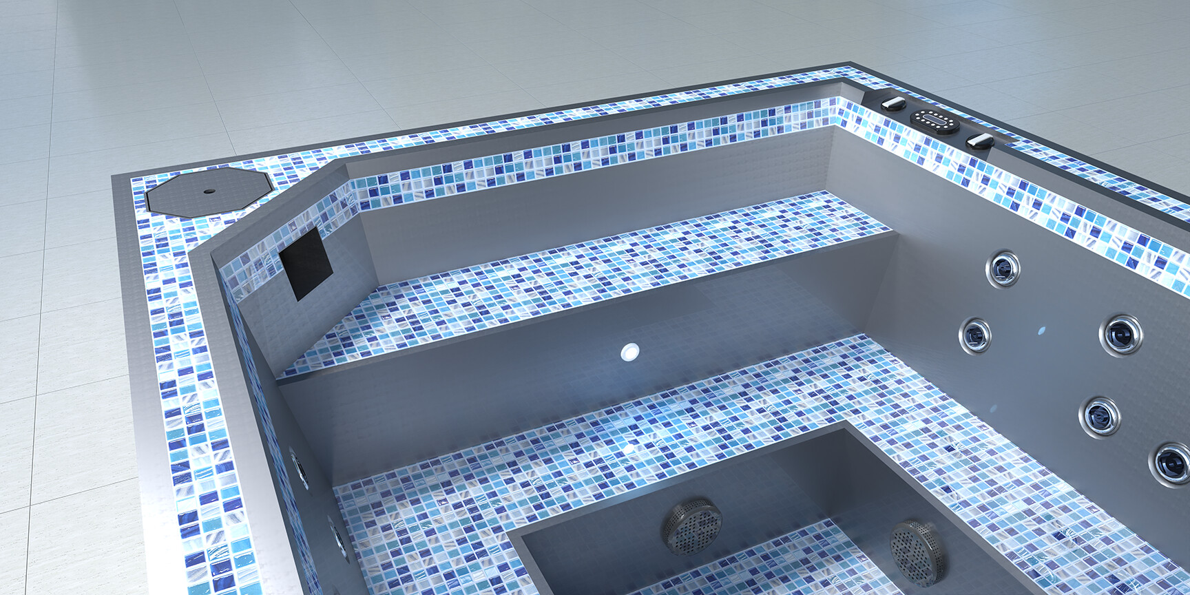
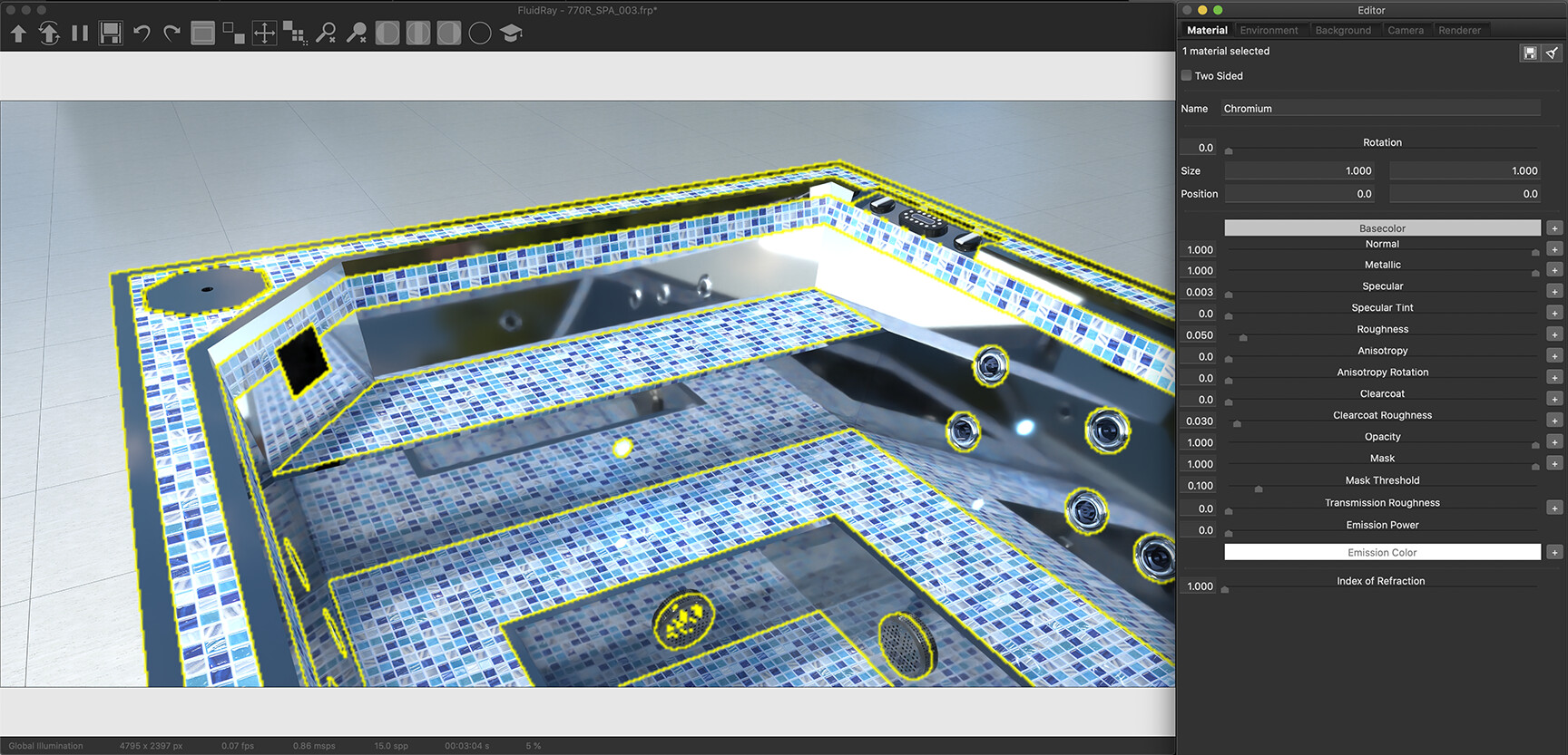
I am trying to understand why the metal material used in this image has such inconsistencies with the reflections in the final render.
I am trying to create a Stainless Steel material, and used the FluidRay Metal09.frm as a starting point to tweak to what I thought resembled the desired outcome. It obviously has some flaws in the final render as shown in the attachments.
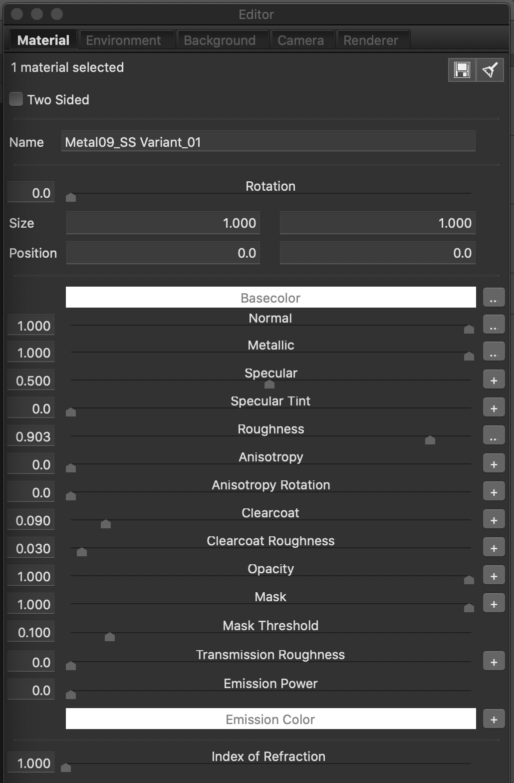
What would be helpful is the ability to see what a standard .FRM material has in its settings WITHOUT having to apply it to the model/scene and have the CPU start a render. Is there a way to do this?
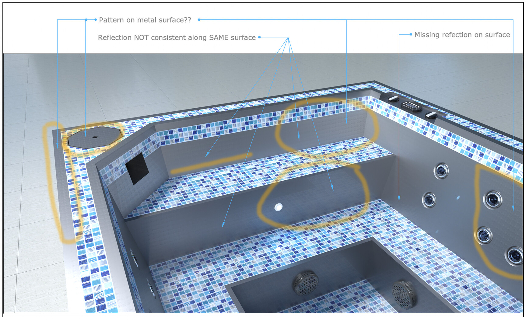
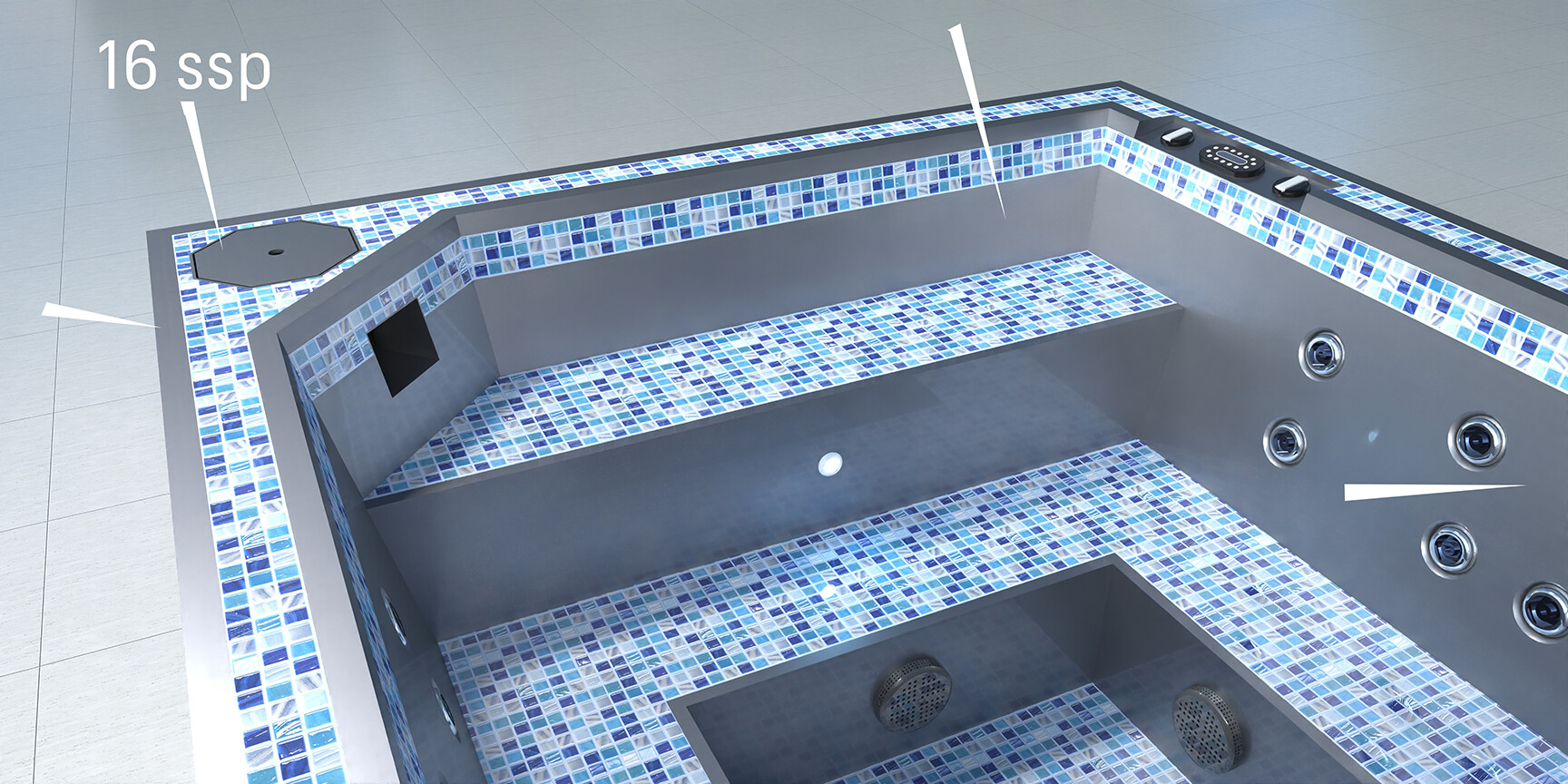
Secondly…I have no idea why the reflections are not consistent across the same metal surface? Such as in the step riser or lack or any reflection of the bench seat in the right side wall with the jets?
Or WHY the metal surface in some places has a reflection at all…as in the case of the Skimmer Lid, showing some sort of texture pattern when it should be the same as all the other metal surface finish.
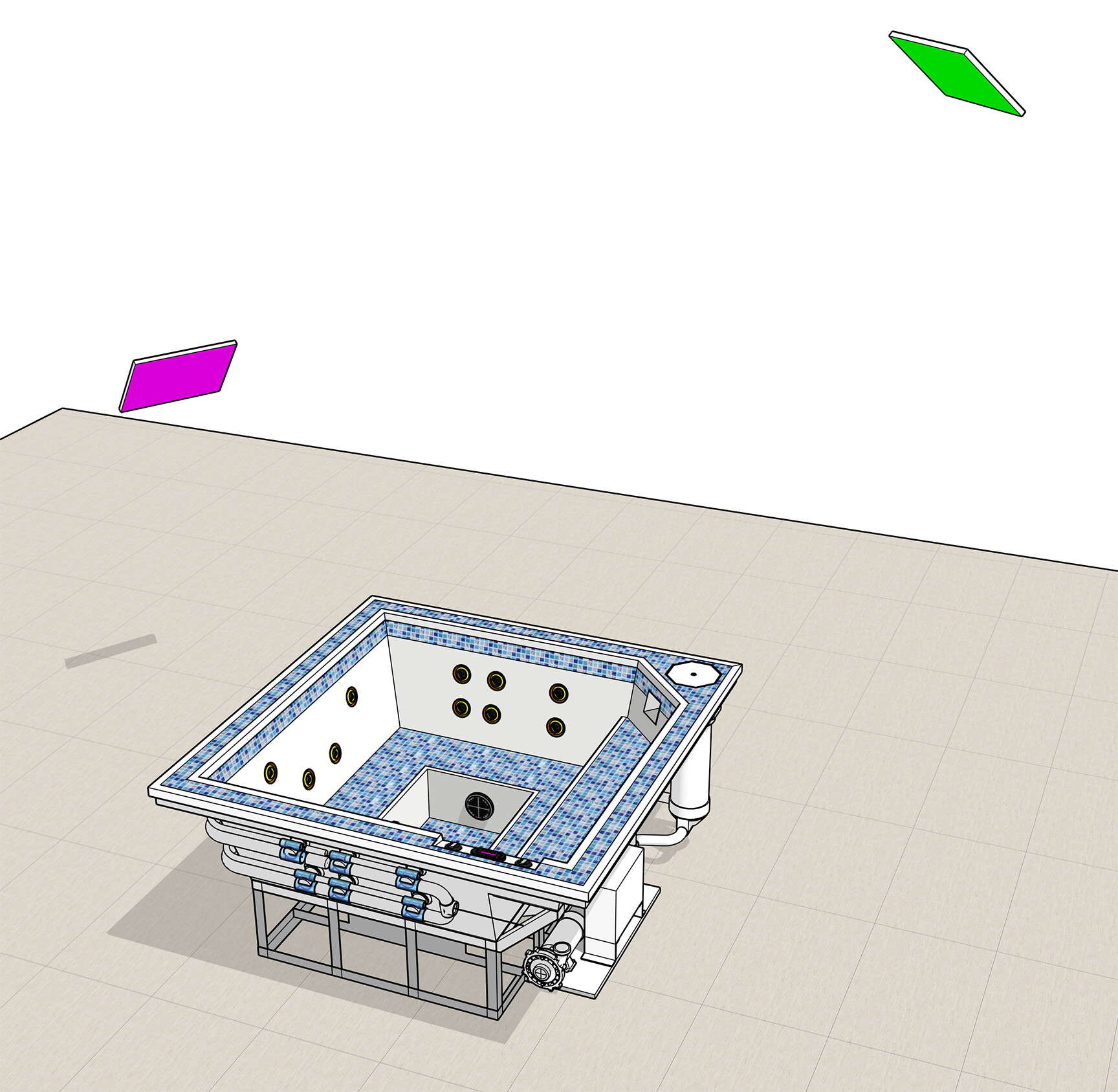
I do have 2 additional light emission surfaces set up to throw some light into the spa interior along with global illumination.!
Where can I find more information / best practices for learning FluidRay??
The metal you used have some textures applied to it. If the material size is too small, that might cause the appearance of some patterns or the other issues you described. You can try increasing the material size, or better yet, use materials from the Polished Metals folder, they come without textures.
We are in the process of adding more documentation / tutorials. You can find the available documentation here:
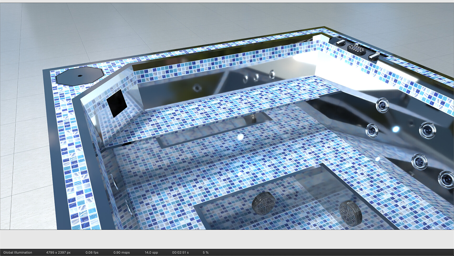
Thanks for the response. Unfortunately the metal material I am trying to emulate is not polished in real life. So that’s why I tried to alter a metal that already had a more matte finish. Since my first message here i played around with the “spp” setting in the Renderer tab. Funny enough the lower the setting ie: 64spp or 16ssp produced way less random patterns than the higher spp settings.
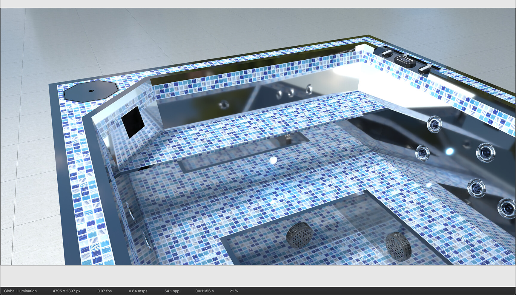
So i guess I would like to know what the “spp” setting is meant to affect, or what it does? See the vast difference between 16spp and 1024spp.
Do you have any idea why the same metal material used, has reflections in some areas (on the same surface) and not in others? Look at the area above the top step tread, there should be reflection of the tile on that metal surface. Also there is some reflection on the next step riser down (to right of image) but missing to the left on the same vertical surface?
Any thoughts on that?
I have watched all the videos on the provided link, so now I am looking for more technical information at the intermediate to advanced level.
Another question I have…Is there any way to preview materials settings without having to apply them to the model scene?
“spp” means “Samples per Pixel”. It’s a measure of the rendering quality. The more samples per pixels, the higher the quality.
The reason why you don’t see the pattern at a lower spp, is because the render quality is lower, and somewhat more blurry. As the rendering quality increases, the finer details start to appear, such as the patterns mentioned above.
I’d still use one of the polished metals as a starting point. Try to increase the roughness parameter, that might be enough to achieve the unpolished look you need.
If you really want to use the other textured metals, try increasing the size to 10x or 100x, and see if that makes the difference.
Currently you have to apply materials to an object to see their different settings.
If a FRM default material has a size of “1” is that an indication of its real-world texture? I guess as I size the material up, i’m trying to understand what the original material was sized at, thereby making arbitrary increases to the default, say 10x or 100x…does that now mean the material is 10x the real world equivalent? With metals this is something that is hard to gauge.
For example, if I was sizing up say a brick material we know the actual brick may be 3" x 7" - or a wooden floorboard material with a width of 3-4"…with the metal, I have know idea of what “size 1” is in relation too?
Any thoughts on why the reflections are not consistent in the metal surface?
That’s a scale multiplication factor. If the value is “1”, the rendered size is the same as the size you had in SketchUp. If it is “2”, the rendered size is twice the size you had in SketchUp.
You can also apply temporarily a FluidRay material that has a more distinctive pattern, such as bricks and get a rough idea of what the proper size is. Then apply the metal and use the size you used previously for the bricks.
The reflections are not consistent because the render quality is low and the material scale is wrong. Once those issues are fixed, the final result should be pretty consistent.
Also, with the key combination Ctrl+2 (Cmd+2 on Mac) you can switch to the Albedo render mode. There you’ll be able to see the texture pattern more clearly.
Ctrl + 1 to return to Global Illumination render mode.
I guess that’s what I’m asking… As I used the default FRM materiel metal, which has a default of “1” in size, is that “1” size suggesting that the metal material is already at real-world size?
It sounds, like this may not be the case, as you mention with your brick pattern exercise.
Remember I am not using the SketchUp material here…but one of the FluidRay standards, that I altered other variables but not the original size of “1”.
hi,
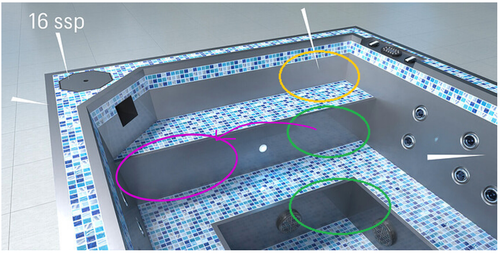
i think that you cant have same reflections in yellow circle as in greens because it is not vertical surface
and as about pattern i cant help, i am often using oversized textuters rather than 1x1
nice model tho
It also sounds a bit hit-and-mis, in the fact that we have no idea of what the actual brick size in any given FRM material is, apart from looking at the applied texture and guessing the “rough” size in relation to any known size element of the model.
Hi…yes you are right, there will be slightly different angle of reflection in the yellow ellipse area due to the fact that the surface here is not 90% vertical. But if you look at the far left of that surface under the black opening for the skimmer, we see some realistic reflections here on this same material, and angled surface.
My main area of concern is why does the reflection in the stair riser (to the right of the light, and in your top green ellipse) display rather accurately, but in my magenta ellipse there seems to be washed out reflection to none at all?
I am playing around now with scale of material size, to see how that affects the render.
Thanks for your compliment on the model. I design aquatic vessels, pools, spas, wet areas for hotels and resorts. We manufacture out of non-polished stainless steel, so is rather critical that I develop a good “real-world” material texture that behaves as it would for our presentations of concept designs etc.
I haven’t even begun to figure out the water and caustics that i’ll need for convincing pre-viz renders. Wish me luck.
I think FluidRay has the potential to deliver what I need, I love the CPU renders Vs. GPU. And I’m tired of Twinmotion 2020.1 crashing all the time.
Certain areas take a bit longer to clear up, that’s probably why the reflections in the magenta circle look a bit blurrier. Try rendering at 64 or 256 spp, that should make a big difference
Also, the material size is always determined by what you have in SketchUp. Even if you don’t assign any material in SketchUp, a default material will be automatically assigned.
It’s a good practice to assign a material in SketchUp even if you plan to override it later in FluidRay. In this way you have the initial size roughly right. You then make small adjustments with the “Size” parameter in FluidRay.
Interesting… If I know my tiles are 1"x1" then i could fill all the metal surfaces in the model with another 1x1 tile, in effect making the SKP texture true size. Hmmmmm???
waiting on those tests now…with the lack of a stainless steel polished material, I have to try to turn other FRM materials into the stainless satin look. Though now it would make sense for me to go back to the SKP model and make sure the metal surfaces are scaled right, before trying all the variables in altering a polished metal FRM material.
How much does the Normal Bump map setting affect a polished metal…or should I leave that setting along and adjust the roughness slider to decrease the polished effect?
With regards to making the Chromium look less “polished” are you saying leave the “normal” slider in its default setting and just adjust the roughness slider?
I’d love to have a chart or info on what all the sliders do, in regards to their effect in FluidRay. As I am Googling all the terms and I get all the other render software / engines and how they handle or use the terms.